
Broken Part Recovery: 3D Scanning, Reverse Engineering and Precise 3D Printing
A cracked housing, a snapped bracket, a damaged heat sink cover — in any production environment these failures happen daily. The real problem begins when the part is no longer manufactured, the supplier is unreachable, or the lead time for a replacement stretches into weeks. This is exactly where DRUKEX delivers: 3D scanning of the damaged component, digital reconstruction of the broken geometry, and 3D printing of a finished part in a material matched to your specific operating conditions.
In this article we walk through the full process step by step — what technologies are used, which materials are available, and in which situations this approach delivers the best results for industrial and commercial clients.
Why Broken or Obsolete Parts Are a Serious Business Problem
Every production line, every machine, every industrial device is built from hundreds of components. Many are standard catalogue items — easy to source and replace. But a significant number are unique: custom-shaped housings, application-specific brackets, protective covers with complex geometry. When one of these fails, your business typically faces one of the following scenarios:
- The OEM has discontinued the part — no replacement exists anywhere on the market.
- Minimum order quantities are impractical — the supplier will only produce a batch of 500, but you need just one.
- Lead times are critical — traditional CNC milling or injection moulding takes weeks, while your line stands idle.
- Only a damaged original exists — there are no drawings, no CAD files, no technical documentation whatsoever.
For all of these situations, DRUKEX has developed a full-cycle part recovery service: from 3D scanning through to a finished, functional component.
Step 1: 3D Scanning the Damaged Component
The process begins with 3D scanning of the broken part. Even when a section has fully snapped off, the scanner captures all remaining geometry to an accuracy of tenths of a millimetre. This stage replaces manual measurements entirely and eliminates the dimensional errors that are inevitable with traditional hand-measurement approaches.
What 3D Scanning Delivers
A professional 3D scanner generates a point cloud — a digital representation of the physical object built from millions of surface measurements. From this data, a polygonal mesh is created that accurately reproduces the part’s geometry.
For broken part recovery, this means:
- Symmetrical fractures — the missing section is reconstructed by mirroring the intact geometry.
- Unique or asymmetric geometry — the engineer analyses the design logic and reconstructs absent features based on contextual clues: mating surfaces, fixing holes, blend radii.
- Multiple damaged specimens — scan data from several broken examples is combined to assemble a complete geometric picture.
The output of this stage is a digital file ready to pass into CAD reconstruction.
Step 2: CAD Reverse Engineering — Reconstructing the Broken Section
The polygonal mesh from the scan is imported into SolidWorks, a professional parametric CAD modelling environment. Here DRUKEX engineers carry out the most demanding part of the workflow: digital reconstruction of the missing or damaged features.
How Broken Sections Are Rebuilt
The reconstruction approach depends on the extent of the damage:
Partial fracture (for example, a snapped lug on a bracket or a broken rib): the engineer analyses the surviving geometry, identifies the fracture line, and reconstructs the missing feature in line with the original form and function.
Extensive housing damage: where a large section is missing, the team uses design symmetry, functional reference features (holes, mating surfaces) and product logic to reproduce the full geometry.
Worn surfaces: for parts that are not broken but critically worn, the CAD model is adjusted back to nominal dimensions, restoring original functionality.
Once reconstruction is complete, the model is validated: wall thicknesses, fillet radii, draft angles and other parameters relevant to print quality are all reviewed before moving forward.
Step 3: Material Selection — The Critical Decision for Part Performance
One of the core advantages of FDM (Fused Deposition Modelling) technology is the breadth of available materials, each with distinct mechanical and thermal properties. Choosing the right material for a recovered part is just as important as geometric accuracy.
A full overview of available options can be found on the 3D printing materials page.
Key Materials for Functional Part Recovery
ASA (Acrylonitrile Styrene Acrylate)
The preferred choice for external housings and parts exposed to outdoor conditions or elevated temperatures. Excellent UV resistance, thermal stability up to 95–100°C, and strong mechanical performance. Ideal for recovering industrial lighting housings, heat sink covers and protective enclosures.
ABS (Acrylonitrile Butadiene Styrene)
The established workhorse for technical components. High rigidity, good post-processing compatibility (sanding, bonding, painting). Well suited to electronics enclosures, brackets and interior machine components.
PETG (Polyethylene Terephthalate Glycol)
A well-balanced engineering material: better impact resistance than ABS, lower shrinkage, and good chemical resistance. Used for parts in contact with liquids or mild chemicals.
Nylon (Polyamide)
For high-wear, high-friction applications: gears, bushings, sliding components. Combines flexibility with strong mechanical load capacity.
TPU (Thermoplastic Polyurethane)
A flexible material for seals, protective pads and parts requiring vibration damping or compressibility.
PC (Polycarbonate)
The highest thermal stability of standard FDM materials (up to 110–130°C), combined with excellent impact resistance. Suitable for structurally demanding components in high-temperature environments.
Case Study: Recovering a Finned Heat Sink Housing
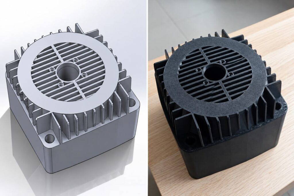
Consider a concrete example: recovery of a heat sink housing for an industrial LED lighting unit. The part has complex geometry — vertical cooling fins, a central mounting bore, a louvred ventilation structure and symmetric fixing holes.
After the unit was dropped, several fins were completely snapped off and the top plate had developed a crack. The lighting manufacturer no longer produces this model, and sourcing an equivalent replacement would have taken months.
The DRUKEX solution:
- 3D scanning of the surviving housing section — capturing precise geometry of the fins, bores and mounting surfaces.
- CAD reconstruction in SolidWorks — broken fins rebuilt using symmetry and surviving fragments; the crack resolved in the digital model.
- Material selection — black ASA: high thermal stability for proximity to the LED module, UV resistance for outdoor use, and a matte surface finish.
- FDM 3D printing with optimised part orientation — fins printed vertically to maximise strength along the primary load axis.
- Post-processing — light sanding of mating surfaces to ensure precise fit on reassembly.
Result: a fully functional housing, geometrically identical to the original, ready for installation within 3 working days.
When 3D Scanning and FDM Printing Is the Right Solution
This approach is not universally the optimal answer. Here are the criteria that make scan-based reverse engineering and FDM 3D printing the best choice:
Ideal Applications
- Obsolete or discontinued parts — where no alternative supply source exists.
- Single units or small series — from one part to several dozen; small-series production on FDM systems is economically viable even for the smallest quantities.
- Plastic housings and enclosures — where metal-grade strength is not required but accurate geometry is essential.
- Rapid prototyping before final production — a prototype is printed first to verify fit and function, then the production part is manufactured.
- No documentation available — no drawings, no 3D files, no original specifications.
When to Consider Alternative Approaches
- The part is subject to extreme structural loads requiring metal-grade strength → CNC milling is the better route.
- Thousands of identical parts are required → injection moulding will be more cost-effective at scale.
- The part operates continuously above 150°C → specialist high-performance polymers or metal components should be specified.
The Advantages of DRUKEX’s End-to-End Service
The primary advantage of working with DRUKEX is a fully integrated, single-source workflow. Clients do not need to coordinate separately between a scanning bureau, a CAD engineering firm and a print service provider. The entire process — from first contact to finished part — is handled by the DRUKEX team in Siemianowice Śląskie.
For clients from Katowice, Chorzów, Bytom, Sosnowiec and across the Upper Silesia region, this means being able to bring a damaged part in person, discuss technical requirements directly with engineers, and collect the finished component without complex logistics. Further information about regional services is available on the 3D printing Katowice page.
What Clients Receive
- Speed: from part receipt to finished component in 2 to 5 business days, depending on complexity.
- Accuracy: recovered part geometry matches the original to within ±0.2 mm.
- Material flexibility: selection from 7+ FDM materials matched to operational requirements.
- Documentation: the client receives the CAD file of the reconstructed part for repeat orders or internal archiving.
- Transparent pricing: a detailed quote is agreed before any work begins.
Frequently Asked Questions About Part Recovery
Can a part be recovered if more than half of it is missing?
Yes, depending on the specific geometry. If at least half of the part survives, or if characteristic reference features remain (holes, slots, mating surfaces), engineers can reconstruct the full form. In complex cases, we provide a preliminary feasibility assessment before any commitment is made.
How does the strength of a recovered part compare to the original?
Strength depends on material choice and print orientation. For the majority of housings and brackets, FDM parts in ABS or ASA provide entirely adequate strength for normal service conditions. For structurally loaded components, Nylon or PC is recommended — and in some cases a combination of 3D printing with post-processing or reinforcement inserts may be the optimal solution.
Does the damaged part need to be brought in person?
No. Parts can be sent by post or courier. After scanning and model approval, the finished component is shipped back to the client anywhere in Poland.
What if the same part is needed repeatedly?
Once a part has been recovered, the CAD file is retained. Repeat orders can be fulfilled without rescanning. For batches of 10 units or more, we calculate optimised pricing for series production.
Conclusion: Part Recovery Is Faster and More Affordable Than You Expect
3D scanning combined with CAD reverse engineering and FDM 3D printing makes it possible to recover virtually any plastic component — even from a heavily damaged original. This is not a temporary workaround but a fully functional replacement that, in many cases, outperforms the original part through optimised material selection.
For businesses across Upper Silesia and throughout Poland, DRUKEX offers this service as part of a comprehensive approach to rapid prototyping and component manufacturing — from brief to finished part in minimum time.
Have a broken part that needs recovering? Submit a photo or description via our quote page — our engineers will assess reconstruction feasibility and provide a preliminary price within 24 hours. Don’t wait weeks for a spare part that may not even be available. We can manufacture it faster than you think.